For QwikMD general information, updates, related publications, tutorials and QwikMD applications, please visit QwikMD home page.

Table of Contents

Molecular Dynamics Simulation and QwikMD Top

Molecular dynamics (MD) is a computer simulation of physical movements of atoms and molecules, widely used to study biological systems. The atoms and molecules are allowed to interact, giving a view of the motion of the atoms and consequently of protein domains in the case of protein simulations. MD has emerged as an important research methodology covering systems to the level of millions of atoms.

QwikMD is a VMD plugin to help to start and analyze MD simulations. The plugin helps, specially scientists that are starting to perform MD simulations, to prepare the necessary files to run these simulations in desktop machines all the way to large supercomputers. All the necessary steps, from the PDB to the configuration file is created with simple procedures so the user one can use the plugin to learn how to prepare MD simulations. The live simulation option allows for the visualization and analysis of the simulation on the fly, helping new users to learn more about MD simulations and expert users to test their simulations before submitting it to run in a supercomputer. QwikMD integrates VMD and NAMD, two widely used software developed by the Theoretical and Computational Biophysics Group at University of Illinois at Urbana-Champaign.

QwikMD Library

QwikMD Library is created in the first time QwikMD is open and the name and location are chosen by the user. This folder contains the files used during the system preparation and MD set up and its location is saved in the file .qwikmdrc (Linux & Mac) or qwikmd.rc (Windows). Inside the toppar folder is located a reference table, "toppartable.txt listing the residues and correspondent file, Topology+ParameterFiles.str, containing the topology and parameters for unrecognized residues. The edition of this table and the addition of *.str files must be done through QwikMD using the "Add Topo+Param" button in the Structure Manipulation/Check window. The folder templates contains the NAMD configuration files used to set up the simulation in the "Advanced Run". The folders Vacuum, Implicit and Explicit store the configuration files modified by the user for the specific solvent model to be employed. Any *.conf file added to one of these folders (Vacuum, Implicit or Explicit) will be recognized by QwikMD and can be used to set up MD simulations in the "Advanced Run".

WARNING: QwikMD relies on file format and integrity. To add or change configurations files, one must keep the file format and pay special attention in case of using scripting inside the configuration file, one must open and close brackets within the same row, and the use of variables must be avoided for keyword values such "run".

QwikMD Library structure

  • .qwikmdrc (Linux & Mac) or qwikmd.rc (Windows)
  • QwikMDLibraryFolder
    • toppar
      • toppartable.txt
      • Topology+ParameterFiles.str
    • templates
      • Minimization.conf
      • Equilibration.conf
      • Annealing.conf
      • MD.conf
      • SMD.conf
      • Vacuum
      • Implicit
      • Explicit
NAMD (NAnoscale Molecular Dynamics)
Recipient of a 2002 Gordon Bell Award and a 2012 Sidney Fernbach Award, NAMD is a parallel molecular dynamics code designed for high-performance simulation of large biomolecular systems. Based on Charm++ parallel objects, NAMD scales to hundreds of cores for typical simulations and beyond 500,000 cores for the largest simulations. NAMD uses the popular molecular graphics program VMD for simulation setup and trajectory analysis, but is also file-compatible with AMBER, CHARMM, and X-PLOR. NAMD is distributed free of charge with source code. You can build NAMD yourself or download binaries for a wide variety of platforms. To run QwikMD you need NAMD installed in your machine and available in your path.
For LINUX/MAC users
  • Setting the Path: To start to use QwikMD you will need to add the namd2 directory to your path in order for the operational system to locate it. To perform that, add to your .bashrc (Linux) or .Profile (Mac) in your home folder the following line: export PATH =complete_path.for.namd:$PATH. Where (complete.path.for.namd) is the complete path to the actual folder where the namd2 executable is available. Example: export PATH =/usr/local/NAMD_2.11:$PATH If you are new to Linux, visit our guide Unix Tutorial.
For Windows users
  • Setting the Path: To start to use QwikMD you will need to add the namd2 directory to your path in order for Windows to locate it. This can be accomplished by right-clicking Computer on the Desktop and selecting Properties - Advanced system settings - Advanced - Environment Variables (the precise procedure may vary depending on your version of Windows). Under System variables, scroll down and select Path and then Edit. At the end of the long line in Variable Value, add a semi-colon ; then the full path to the directory containing namd2 (but do NOT add the executable "namd2" at the end). Click OK. Now open a new command prompt. Regardless of the directory you are in, you should be able to type namd2 and run it.
Setting up a Molecular Dynamics Simulation
In order to run any MD simulation, NAMD requires at least four files:
  1. Protein Data Bank (pdb) file which stores atomic coordinates and/or velocities for the system. Pdb files are available for many proteins at www.pdb.org, or can be generated using structure modeling software.
  2. Protein Structure File (psf) which stores structural information of the protein, such as various types of bonding interactions.
  3. Force field parameter file. A force field is a mathematical expression of the potential which atoms in the system experience. CHARMM, X-PLOR, AMBER and GROMOS are four types of force fields which can be employed in NAMD. The parameter file defines bond strengths, equilibrium lengths, etc.
  4. NAMD configuration file, in which the user specifies all the options to be loaded into NAMD to run a simulation. The configuration file tells NAMD how to run the simulation.
The PDB files
The term PDB can refers to the Protein Data Bank, to a protein structure file stored in the webserver, or to a file following the PDB format. Files in the PDB include information such as the name of the compound, authorship and general structure publication information, amino acid sequence, stoichiometry, and the ATOM and HETATM records containing the coordinates of the protein and any water, ion, or other heterogeneous atoms in the crystal. Some PDB files include multiple sets of coordinates for some or all atoms. Due to the limits of x-ray crystallography and NMR structure analysis, the coordinates of hydrogen atoms are usually not included in the PDB. NAMD and VMD ignore everything in a PDB file except for the ATOM and HETATM records, and when writing PDB files the ATOM record type is used for all atoms in the system, including solvent and ions. If one inspects a PDB file, the fields seen in order from left to right are the record type, atom serial number, atom name, alternate location indicator, residue name, chain identifier, residue sequence number, code for insertion of residues, x, y, and z coordinates, occupancy, temperature factor (called beta), element symbol and atom charge (for more information visit PDB file format).
The PSF files
A PSF file, also called a protein structure file, contains all of the molecule specific information needed to apply a particular force field to a molecular system. The CHARMM force field is divided into a topology file, which is needed to generate the PSF file, and a parameter file, which supplies specific numerical values for the generic CHARMM potential function (topology and parameter file can be merged into one stream file). The topology file defines the atom types used in the force field, the atom names, types, bonds, and partial charges of each residue, and any patches necessary to link or otherwise mutate residues. The parameter file provides a mapping between bonded and non-bonded interactions involving the various combinations of atom types found in the topology file and specific spring constants and similar parameters for all of the bond, angle, dihedral, improper, and van der Waals terms in the CHARMM potential function.The PSF file contains six main sections of interest: atoms, bonds, angles, dihedrals, impropers (dihedral force terms used to maintain planarity), and cross-terms. After preparing initial files with QwikMD, one can inspect the PSF file from the "setup" folder in a text editor and check how a PSF file looks like. Note that this "setup" folder is located inside the folder created as working directory when pressing Prepare/Save.
The Parameter files
A CHARMM force field parameter file contains all of the numerical constants needed to evaluate forces and energies, given a PSF structure and atomic coordinates files. The parameter file is closely tied to the topology file that was used to generate the PSF file, and the two are typically distributed together and given matching names. QwikMD uses CHARMM36 force field and its parameter files are available in the "run" folder located inside the folder created as working directory when pressing Prepare/Save.
The NAMD Configuration file
The NAMD configuration file (common extensions *.conf or *.namd) is given to NAMD on the command line and specifies virtually everything about the simulation to be done. The only exceptions are details related to the parallel execution environment, which vary between platforms. Therefore, the configuration file should be portable between machines, platforms, or numbers of processors in a run, as long as the referenced input files are available. QwikMD uses a standard configuration file that uses "safe" parameters set, which will most likely work for the system prepared within QwikMD. The configuration file is available in the "run" folder located inside the created as working directory when pressing Prepare/Save.
How To cite
When using NAMD, VMD and QwikMD please cite the following articles
  • VMD - Visual Molecular Dynamics; William Humphrey, Andrew Dalke, and Klaus Schulten Journal of Molecular Graphics, 14:33-38 (1996) (PMC: 2486339)
  • Scalable molecular dynamics with NAMD; James C. Phillips, Rosemary Braun, Wei Wang, James Gumbart, Emad Tajkhorshid, Elizabeth Villa, Christophe Chipot, Robert D. Skeel, Laxmikant Kale, and Klaus Schulten Journal of Computational Chemistry, 26:1781-1802 (2005) (PMC: 2486339)
  • QwikMD - Integrative Molecular Dynamics Toolkit for Novices and Experts; João V. Ribeiro, Rafael C. Bernardi, Till Rudack, John E. Stone, James C. Phillips, Peter L. Freddolino, and Klaus Schulten. QwikMD-integrative molecular dynamics toolkit for novices and experts. Scientific Reports, 6:26536, 2016. Scientific Reports, 6, 26536110 (2016)
Graphical User Interface Top
QwikMD graphical user interface (gui) offers two modes of usability, "Easy/Basic" and "Advanced" mode, depending on the user experience in preparing ("Run" tabs) and analyzing Molecular Dynamics (MD) Simulations ("Analysis" tabs). On the "Easy/Basic" mode, only basic options can be manipulated by the user, such as temperature and simulation time, whereas on the "Advanced" mode, a plethora of operations is available for experienced users to customize and adapt QwikMD default workflow and variables to their specific needs.
Run Tabs Top

The preparation and submission of the MD simulation take place in the Run tabs (Easy and Advanced). In these tabs, one can select the segments to be simulated, and manipulate the structure to replicate the experimental conditions or to formulate the hypothesis to be tested (e.g. the effects of a point mutation in the structure dynamics).

Selection and visualization components
  • Load Initial Structure: One can select the file containing the atom's coordinates in two different ways: by pressing "Browser", select a local file (.pdb, .mol2, .xyz and etc.) and press "Load"; or by typing the Protein Data Bank structure ID (4-character unique identifier code, i.g. 1kjf for HIV-1 PROTEASE) in the text entry and then press "Load" as well. During the load process, the structure is checked for possible inconsistence, such as non-parameterized residues, protein gaps and etc. (see Structure Check).

  • Selection Menus: Composed by "NMR State" and "Chan/Type Selection" menus, enables the user to select the components of the structure that will be prepared for the MD simulation. For instance, structures obtained by NMR spectroscopy may contain more than one state of the protein; multiple protein chains; different molecule types assigned within the same chain identifier (e.g. protein and nucleic residues of the chain A).

    • NMR State: Select one if the NMR States (frames) available in the loaded structure. Expected values from 0 to [number of states - 1].

    • Chan/Type Selection: Select the residues defined by the atom's selection "Chain Identifier and Molecule Type", such as, "A and protein". User can select/deselect each segment individually or all segments at once by Chain/Type Selection → Select → All/None.

    • Structure Manipulation: Opens the window titled "Structure Manipulation/Check", where most modeling tasks available in QwikMD take place. This window is also involved in other selection tasks such SMD anchoring/pulling residues and MD simulation restraints atom selections.

  • Main Table : Lists all the segments selected in the "Chain/Type Selection" menu. This table presents an overview of the system that will be prepared for the MD simulation, and enables to change the representation and coloring modes of each segment. To change representation or coloring modes, just click over the representation/color of the segment line to be changed and select the option from the drop-down menu. For more information, please visit Rendering methods, Coloring methods and Definition of Keywords and Functions.

  • Background : Changes the color of the "VMD OpenGL Display" background. The Color Scheme modifies the representation color pallet. Currently only the default color scheme is available.

As determinant as the initial structure, the configuration options that feed the MD simulation influence greatly the outcome of the simulation. QwikMD automates the generation of the MD configuration files according to the calculation to be preformed (where known as protocols), such as non-biased MD (where known as "Molecular Dynamics"), Steered MD and MD flexible fitting. For more information regarding the different MD simulations and its specificities, please visit NAMD tutorials.

Easy Run Top
The "Easy Run" was designed to assist MD novices, especially experimentalists, to overcome the initial learning curve barrier hindering general use of MD simulations. Within the Easy Run tab, one can prepare, execute and analyze MD simulations without the hardness of the computational minutia. The default values set in QwikMD were selected to assure robust simulations. However, QwikMD is not a black box, it rather provides the user with access to all underlying structures and NAMD configuration files and offers an opportunity to adjust them individually.
System Solvation Top
To perform MD simulations one has to mimic the environment of the protein, or any other molecule of interest. The most common solvent is water and there are two main ways to mimic the solvent effect. Either simulating all the atoms of the solvent - explicit solvent model - or by adding dielectric constant to the electrostatic calculation - implicit solvent model.
  • Solvents: Select the solvent model to employed: Implicit or Explicit
    • Implicit Solvent: An implicit solvent model is a simulation technique that eliminates the need for explicit water atoms by including many of the effects of solvent in the inter-atomic force calculation. The elimination of explicit water accelerates conformational explorations and increases simulation speed at the cost of not modeling the solvent as accurately as explicit models. QwikMD uses the Generalized Born Implicit Solvent implemented in NAMD.
    • Explicit Solvent: QwikMD uses VMD solvate plugin to generate a cubic box centered in the geometrical center of the system and box's edge is calculated by:

      MD Protocol box : box_{edge} = (\sqrt{x^2+y^2+z^2}) + 15

      SMD Protocol box : box_{x} = box_{y} = (\sqrt{x^2+y^2}) + 15 | box_{z} = z + PullingDistance + 15 .

      , where x,y and z are the dimensions of structure in the three axis. Box dimensions in Å. When preparing the simulation, the simulation is translated to the origin {0,0,0}.

      Note: The water box created by QwikMD is somewhat big for most studies. The big water box was adopted as a safety measure. Ideally, one should work with a box, which is large enough that the protein does not interact with its image in the next cell if periodic boundary conditions are used. The use of periodic boundary conditions involves surrounding the system under study with identical virtual unit cells. The atoms in the surrounding virtual systems interact with atoms in the real system. These modeling conditions are effective in eliminating surface interaction of the water molecules. As the standard water model for CHARMM, TIP3P is the model employed in the simulations prepared with QwikMD.

  • Salt Concentration: Ions should be placed in the water to represent a more typical biological environment. They are especially necessary if the protein being studied carries an excess charge. In that case, the number of ions should be chosen to make the system neutral. One must set the desired salt concentration. The default Salt Concentration is 0.15 mol/L. QwikMD uses VMD autoionize plugin to place the ions and even if the Salt Concentration is set to ZERO, ions will be added to neutralize the total charge of the system. In the case of the Generalized Born implicit solvent, the salt concentration is used as ion concentration parameter value (see Generalized Born Implicit Solvent Configuration Parameters).
  • Choose Salt: Salt ion pairs currently available are NaCl and KCl.
Protocols Top
Within the "Easy Run", the user can set up two types of simulations: non-biased Molecular Dynamics (or just Molecular Dynamics - MD) and Steered Molecular Dynamics (SMD).
MD protocol SMD protocol
  • Temperature: target temperature in degrees Celsius.
  • Simulation Time: Total time of the "MD" step in ηs.

    Note : One can extend (restart) the "MD" step by pressing the "Start" button in the end of the simulation. This will start a new MD simulation from the last point of the previous step with the values of "Temperature" and "Simualtion Time" currently selected.

  • Temperature: target temperature in degrees Celsius.
  • Pulling Residues: opens the window "Select Pulling Residues". Select the residues to be pulled and then press "Apply". The pulling and anchoring residues selection cannot overlap.
  • Anchoring Residues: opens the window "Select Anchoring Residues". Select the residues to be anchored and then press "Apply". The anchoring and pulling residues selection cannot overlap.
  • Pulling Distance: Maximum estimated distance in Å covered by the "Pulling Residues" in the end of the SMD simulation(s). This distance is used to build the water box in the structure preparation phase. Changes in this value after preparing the system will have any effect on the system or in the simulation.
  • Pulling Speed: Pulling constant velocity in Å/ηs of the "Pulling Residues".
  • Simulation Time: Total time of the "SMD" step in ηs.

    Note : One can extend (restart) the "SMD" step by pressing the "Start" button in the end of the simulation. This will start a new SMD simulation from the last point of the previous step with the values of "Temperature", "Pulling Speed" and "Simualtion Time" currently selected.

  • Molecular Dynamics Simulations : Molecular dynamics (MD) is a computer simulation of physical movements of atoms and molecules in the context of N-body simulation. The atoms and molecules are allowed to interact for a period of time, giving a view of the motion of the atoms. In the most common version, the trajectories of atoms and molecules are determined by numerically solving the Newtons equations of motion for a system of interacting particles, where forces between the particles and potential energy are defined by interatomic potentials or molecular mechanics force fields.

    Note : When running MD simulations it is very important to run more than one replica of the same system. Long trajectories usually also helps one to sample different conformations. Therefore a long simulation is important if big conformational changes are expected. If you want to learn more about sampling and molecular dynamics check the link at the bottom of this window.

  • Steered Molecular Dynamics Simulations : Steered molecular dynamics (SMD) simulations, or force probe simulations, apply forces to a protein in order to manipulate its structure by pulling it along desired degrees of freedom. These experiments can be used to reveal structural changes in a protein at the atomic level. SMD is often used to simulate events such as mechanical unfolding or stretching.

    There are two typical protocols of SMD: one in which pulling velocity is held constant and one in which applied force is constant. Typically, part of the studied system (e.g. an amino acid in a protein) is restrained by a harmonic potential. Forces are then applied to specific atoms at either a constant velocity or a constant force in the direction of the pulling axis. QwikMD is set to perform constant velocity SMD.

    The pulling axis is defined by the vector formed by the centers of the selections Anchoring and Pulling Residues. During the system preparation phase, the initial structure pulling axis is aligned with the z-axis and the pulling speed vector assumes only the z component.

  • Equilibration step: This protocol step is composed by 1000 steps of Energy Minimization, a "Temperature Ramp", where the temperature in raised from 60 K to the chosen "Temperature", 1 K/ρs and 1.0 ns of MD simulation. During the equilibration step, the backbone atoms of protein and nucleic residue are restrained in space.

Default Configurations

  • Integration Step: The time step used in any MD simulation should be dictated by the fastest process (i.e. movement of atoms) taking place in the system. Among the various interactions, bond stretching and angle bending are the fastest, with typical bond stretching vibrations occurring on the order of once every 10-100 femtoseconds. Using a time step of 2 fs, which is close to the vibrational period (10 fs) of linear bonds involving hydrogen (fastest vibrations, since hydrogen has small mass), requires that these bonds be fixed, and only slower vibrations may be free to move, such as dihedral angle bending. For large molecules, these slower vibrations typically govern the behavior of the molecule more than the quicker ones, so bond fixing is somewhat acceptable, but should be avoided for accurate simulations. One prefers to use an MD timestep which is ~ 1/10 of the fastest interactions in the simulation. For simulations with time step of 1 fs, one should use rigidBonds for water because water molecules have been parametrized as rigid molecules. QwikMD adopts 2 fs time step as standard.

  • NPT Ensemble : In the isothermal-isobaric ensemble (NPT), number of atoms (N), pressure (P) and temperature (T) are conserved. To do control pressure and temperature a thermostat and a barostat are needed. The NPT ensemble corresponds most closely to laboratory conditions with a flask open to ambient temperature and pressure. Langevin dynamics is a means of controlling the kinetic energy of the system, and thus, controlling the system temperature and/or pressure. QwikMD uses standard NAMD protocols that employ Langevin dynamics.

Advanced Run Top
The "Advanced Run" was designed for experienced users who want to streamline their process of preparing, setting up and preforming MD simulations. In this tab, one has access to more options for solvating the system, more built-in protocols, full access to the MD configuration files as well as the ability to design custom protocols. Selecting the "Advanded Run" tab also activates more options in the Structure Manipulation/Check, such as membrane builder and molecule modifiers (CHARMM forcefield patches).
System Solvation Top
When solvating a particular system, one should to take into account several aspects to ensure that the system does not interact with its image in the next cell if periodic boundary conditions (pbc) are use. The following should be considered during the system solvation process (use of ):
  • Non-bonded interactions cut-off: The distance used in QwikMD by default is 12 Å, meaning that the non-bonded interactions (vdW and electrostatics) are evaluated between particles distanced up to 12 Å. To avoid interactions between the system and its image in neighbor cells, one must select a solvent box big enough that pbc images are distanced more than the non-bonded cut-off distance (see Non-bonded interactions).
  • Rotation/tumble: Systems can rotate/tumble during simulation, which can lead to the "self interaction" with its image in the neighbor cell. Specially critical in non-globular systems elongated in one of the axis, one can easily face inconsistencies if a simple padding (buffer) distance is used surrounding the system.
  • Conformational Changes: If simulations are carried for timescales long enough, ηs to μs (nano to microseconds), large conformational changes can occur, expanding the area occupied by the system.
System solvation options
  • Solvent: Select the solvent model to employed: Vacuum, Implicit or Explicit
    • Vacuum: Absence of solvent and commonly know as simulation in gas phase. Non-bonded interactions cutoff distances are updated to: cutoff: 16 Å, switchdist: 15 Å, pairlistdist: 18 Å. When selected, QwikMD also applies a dielectric constant of 80.0.
    • Implicit Solvent: QwikMD uses the Generalized Born Implicit Solvent implemented in NAMD. Non-bonded interactions cutoff distances are updated to: cutoff: 16 Å, switchdist: 15 Å, pairlistdist: 18 Å and an alphaCutoff: 18 Å is used. A solventDielectric: 80 Å is used to represent water as solvent.
    • Explicit Solvent: QwikMD uses VMD solvate plugin to generate a water box centered in the geometrical center of the system and box's edge is calculated by:

      MD/MDFF Protocol box : box_{edge} = (\sqrt{x^2+y^2+z^2}) + 2 * Buffer

      SMD Protocol box : box_{x} = box_{y} = (\sqrt{x^2+y^2}) + 2 * Buffer | box_{z} = z + PullingDistance + 2 * Buffer .

      , where x,y and z are the dimensions of structure in the three axis ("Minimal Box" option off). Box dimensions in Å. When preparing the simulation, the simulation cell is translated to the origin {0,0,0} except in "MDFF" protocol.

      Note: The water box created by QwikMD is somewhat big for most studies. The big water box was adopted as a safety measure. Ideally, one should work with a box, which is large enough that the protein does not interact with its image in the next cell if periodic boundary conditions are used. The use of periodic boundary conditions involves surrounding the system under study with identical virtual unit cells. The atoms in the surrounding virtual systems interact with atoms in the real system. These modeling conditions are effective in eliminating surface interaction of the water molecules. As the standard water model for CHARMM, TIP3P is the model employed in the simulations prepared with QwikMD.

  • Minimal Box: Rotate the system and apply a simple solvent box padding distance, instead of the formula described in the "MD/MDFF Protocol box" description. The usage of this option should be used carefully and the "Buffer" distance should be increased to account system rotation/tumble during the simulation (see VMD solvate plugin).
  • Salt Concentration: Ions should be placed in the water to represent a more typical biological environment. They are especially necessary if the protein being studied carries an excess charge. In that case, the number of ions should be chosen to make the system neutral. One must set the desired salt concentration. The default Salt Concentration is 0.15 mol/L. QwikMD uses VMD autoionize plugin to place the ions and even if the Salt Concentration is set to ZERO, ions will be added to neutralize the total charge of the system. In the case of the Generalized Born implicit solvent, the salt concentration is used as ion concentration parameter value (see Generalized Born Implicit Solvent Configuration Parameters).
  • Choose Salt: Salt ion pairs currently available are NaCl and KCl.
Protocols Top
Within the "Advanced Run", the user can set up the following types of simulation: non-biased Molecular Dynamics (or just Molecular Dynamics - MD), Steered Molecular Dynamics (SMD) and Molecular Dynamics Flexible Fitting (MDFF).
MD & SMD protocol
  • Protocol: name of the protocol step. To select a different protocol step, one must select the cell and choose one of the options listed in the dropdown menu. The dropdown menu is populated with the default steps: Minimization, Annealing, Equilibration and MD/SMD (depending on the protocol selected). Adding to this list are the saved protocol setps specific for the solvent model selected (see Edit button description below). The default protocol steps can be used once, with the exception of the MD and SMD steps.
  • n Steps: number of steps to be simulated.
  • Restraints: atom selection where harmonic restraining forces will be applied. Upon cell selection, a dropdown menu will display pre-defined selections and also the "From List" option, where the user can select the atoms/residues from the "Structure Manipulation/Check".
  • Ensemble: select the thermodynamic ensemble to run the simulation: NVE,NVT or NpT.
  • Temp (C): target temperature in degrees Celsius.
  • Pressure: target pressure in degrees atmospheres (atm).
  • Clear button: reset the protocol steps list and the delete the files created during the protocol "Edit" process.
  • Unlock button: allow (unlock) or prevent (lock) protocol step from automatic edition by QwikMD. Locking the protocol step is specially useful for custom configuration files added by the user. Every non-default protocol step is "locked" when added to the table as well as the extension/restart steps, e.g., MD.1 MD.2.
  • Edit button: edit configuration file in text mode. This button generates the configuration file where one can manually change and adapt the parameters used by QwikMD. This file is stored in the temporary folder until the preparation process, where is copied to the "run" folder in the working directory. The new generated configuration file can be stored as a template for future use by selecting the option "Save as template for future use" in the pop-up window, and the name changed to distinguish from the default protocol steps. Every created template is specific for the solvent model selected, which means that a template created for the explicit solvent will be only available for explicit solvent simulations (see QwikMD Library).
    • Add special configuration files: Besides the manual edition of the configuration files through the "Edit button", one can add configuration files to QwikMD library.
    • Manual edition: special attention is requires when changing or adding configuration files:
      • In case of using scripting inside the configuration file, one must open and close brackets within the same row;
      • Must no use variables for keyword values such "run".
  • "+/-" buttons: Add or delete protocol steps. If the MD, SMD or a user defined step is selected before pressing the "+" button, an extension step of the selected step is created and renamed as "ProtocolStep".[order in the sequence], for example, MD MD.1 MD.2 and etc.
SMD protocol
  • Pulling Residues: opens the window "Select Pulling Residues". Select the residues to be pulled and then press "Apply". The pulling and anchoring residues selection cannot overlap.
  • Anchoring Residues: opens the window "Select Anchoring Residues". Select the residues to be anchored and then press "Apply". The anchoring and pulling residues selection cannot overlap.
  • Pulling Distance: Maximum estimated distance in Å covered by the "Pulling Residues" in the end of the SMD simulation(s). This distance is used to build the water box in the structure preparation phase. Changes in this value after preparing the system will have any effect on the system or in the simulation.
  • Pulling Speed: Pulling constant velocity in Å/ηs of the "Pulling Residues".
MDFF protocol
  • Temperature: target temperature in degrees Celsius.
  • Minimization Steps: number of steps for the conjugate gradient minimization calculation.
  • MDFF Steps: Number of steps to be simulated (same as nSteps).
  • Fixed: atom selection defining the atoms to be fixed in space.
  • Sec Structure: atom selection defining the atoms to apply Secondary Structure Restraints.
  • Chirality: atom selection defining the atoms to apply Chirality Restraints.
  • Cispeptide: atom selection defining the atoms to apply Cispeptide Restraints.
  • For more MDFF information please visit MDFF webpage
  • Molecular Dynamics Flexible Fitting: the Molecular Dynamics Flexible Fitting (MDFF) method can be used to flexibly fit atomic structures into density maps, specially cryo-electron microscopy (cryo-EM) maps. cryo-EM can capture large macromolecular complexes at different functional states usually inaccessible to X-ray crystallography techniques. However, the resolution of these maps are considerable lower when compared to the X-ray structures. Combine both structural data from different sources and resolutions allow the user to have a high resolution atomic structure representing the conformational state captured on the cryo-EM map.

    Note : Despite of preparing the system with QwikMD, the user is redirected to the MDFF GUI to set up, perform and analyze the simulation.

Structure Manipulation/Check Top
The "Structure Manipulation" button (see Run Tabs) opens the window titled "Structure Manipulation/Check", where most modeling tasks available in QwikMD take place. This window is also involved in other selection tasks such SMD anchoring/pulling residues and MD simulation restraints atom selections.
By selecting a residue, one can preform point mutations, assign protonation states, delete/add residues, rename the residues to match the residue's name in the topology files, modify individual atoms of one residue and change residue's type to match the proper molecule category as protein, nucleic, glycan, hetero and water residues. Topology and parameters information and new molecules types can be added in "Add Topo+Param". In the case of protein residues, the column "type" is colored by the secondary structure correspondent to each residue (color reference in the "Sec. Struct colors" box).
The amount of options available in the "Structure Manipulation/Check" window is dependent on the level mode currently selected (Easy or Advanced Run). As shown in the image below, more options are available when the advanced mode is selected like the possibility to select residues using atom selections text, build a bilayer membrane as well as apply special molecule modifiers available on CHARMM forcefield (commonly known as patches, see VMD psfgen Plugin).
Invoked from Easy Run Invoked from Advanced Run
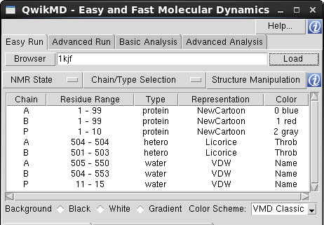
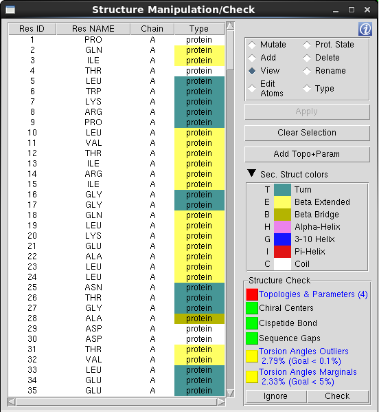
  • Residues Table: The Residues Table is main component of the "Structure Manipulation/Check" window and lists all the residues included in the selection made on "Chain/Type Selection" menu. The residues are listed in the same order as in the "Main Table", which is the order the residues are listed in the initial structure file. To facilitate the browsing through the residues list, one can change the sort criteria and sort the table by a specific column pressing the columns header.

    Residues Marked in Red: When the residue is not recognized by QwikMD, meaning that the specific residue name doesn't match the residue names contained in the Topology files loaded by QwikMD. One must add the stream file containing the topology and the parameters, rename, change the residue type or delete the residue.

  • Table Options: The action triggered when a residue is selected on the Residues Table is determined by the table option selected. One should always select the table option first and then the residue(s) to be manipulated/visualized.
    • Mutate: Mark one residue to be mutated during the structure preparation phase. The mutations are only available for protein and nucleic residues and are dependent on the residue type, for instance, a protein residue can only be mutated to another protein residue.
    • WARNING: Even a very small number of mutations may affect the structure of a protein drastically. Be very careful when using the mutation tool of QwikMD as you might create artifacts in your simulation.

    • Prot. State: Mark one residue to assign a protonation state during the structure preparation phase. Amino acids, depending on their environment, can present different protonation states. It is recommended to check the protonation state of the amino acids before an MD simulation. Several tools can be used for that. One of the most popular tools is the PROPKA Server. The assignment of protonation states is only available for protein residues and the options available are dependent on the residue selected, e.g., only two options are available for the aspartic acid (ASP), neutral (ASP) or protonated (ASPP) state.
    • Histidine Residues: Of the 20 amino acids, histidine is the only one that ionizes within the physiological pH range ~7.4. This effect is characterized by the pKa of the amino acid side chain. For histidine, the value is 6.04. This leads to the possibility of different protonation states for histidine residues in a protein, and makes the consideration of the proper state important in MD simulations. The viable states are one in which the delta nitrogen of histidine is protonated - listed with residue name HSD - one in which the epsilon nitrogen of histidine is protonated - HSE - and one in which both nitrogens are protonated - HSP. If not set by the user, QwikMD uses HSD as the standard histidine protonation state.

    • Add: Add residue(s) previously marked to be deleted.
    • Delete: Mark residue(s) to be deleted during the preparation phase.
    • View: Disable all manipulation options and only represent the selected residue(s).
    • Rename: Change the residue name to match the residue names in the CHARMM forcefield topology files. The possibilities available to rename the selected residue are dependent on the residue type, such as a protein residue can only be renamed to a residue categorized as a protein residue. If the proper residue name is not available, one must add the correspondent Topology+ParameterFiles.str, change the residue type and further rename or delete the residue.
    • WARNING: The structure preparation phase cannot start while the system contains unrecognized residues.

    • Type: Sometimes, molecules categorization can be misleading (or even nonexistent), which hinders the correct identification of residues. For instance, if the user intends to mutate the nucleotide Adenosine Triphosphate (ATP) by another nucleotide, it would be possible to mutate to a Guanine, Adenine, Cytosine or Thymine (or Uracil in RNA), as they share the same category as nucleic residues (nucleic). To avoid such structural errors, QwikMD gives the possibility to change residues type (category), so a logical choice can be made.
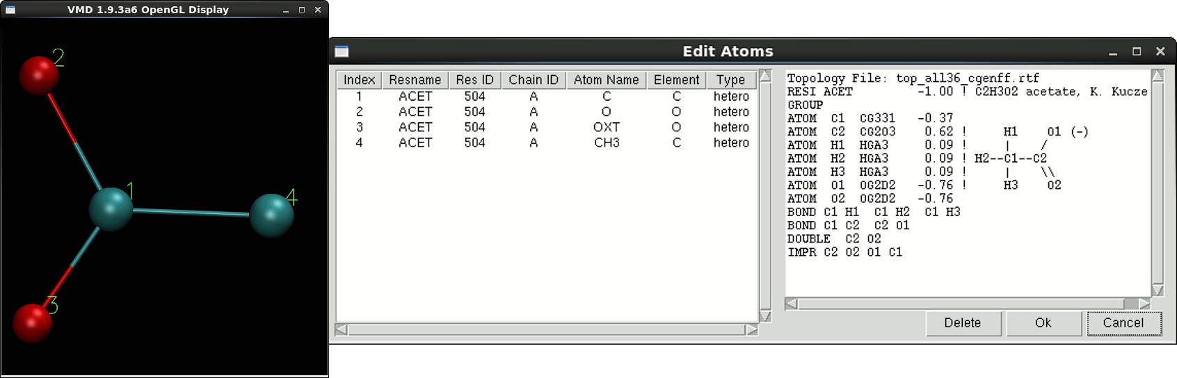
    • Edit Atoms: Residues fine grained edition, where one can change the residue number (resid), the atom's name and delete one or more atoms. Taking the example of the acetate residues in the HIV-1 protease structure (pdb entry 1KJF). The residue name in the original pdb structure is ACT and is marked as unrecognized by QwikMD since the same residue is named as ACET in the CHARMM topology file. In this case, one must change the residue name from ACT to ACET, which raises another topological issue, where none of the atoms name in the pdb match the atoms name the topology. In this case, one must rename also the atoms. For reference purpose, the topology entry and a numbered molecular representation of the residue is given to user.
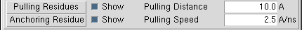
  • Apply/Edit button: Apply residues selection during the SMD Anchoring/Pulling residues selection or open the "Edit Atoms" window when the "Edit Atoms" option is selected.
  • Clear Selection: Deselect the current selected residues.
Topology & Parameters Selection Top
QwikMD doesn't lists all the residues present in the CHARMM 36 topology files by default for simplicity purposes, due to the vast list of residues available. If one needs to add more standard residues to QwikMD list, such as, proteins, nucleotides, carbohydrates (glycan), lipids or other standard residues, one must upload only the topology file (if the parameters are already included in the files loaded in QwikMD by the default) correspondent to the residue type and select the residue from the table.

If the system to be prepared includes one or more residues requiring special topologies and parameters, one must add a stream file (*.str) containing both residue's topology and parameters information.
  • Default Topology files:
    • top_all36_carb.rtf, top_all36_cgenff.rtf, top_all36_hybrid.inp, top_all36_lipid.rtf, top_all36_na.rtf, top_all36_prot.rtf
  • Default Stream files:
    • toppar_all36_carb_glycopeptide.str, toppar_water_ions_namd.str
  • Default Parameters files:
      par_all36_carb.prm, par_all36_cgenff.prm, par_all36_lipid.prm, par_all36_na.prm, par_all36_prot.prm

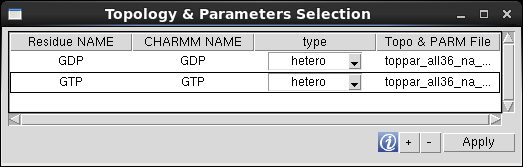
To add the information regarding a special residue, one must press the "+" button and select the *.str file. QwikMD analyzes the file and list the residues ("RESI" keyword) and stores a copy in the QwikMD library folder.
  • Residue NAME: name to be displayed in QwikMD residues list. Protein and nucleic residues must have the same "Residue NAME" and "CHARMM NAME", while hetero, glycan and user defined residue types can assume different residues names, such as, the acetate ion residue: "Residue NAME"=Acetate", "CHARMM NAME"= "ACET".
  • CHARMM NAME: residue name in the CHARMM topology file. Note: Sometime the residues' name listed in the CHARMM topology files can be composed by more than 4 characters, which is a violation of the pdb file format. In this case, a warning message is prompted to the user and the correspondent line of the residue colored in red and one must rename the "CHARMM NAME" to a unique 4 letter residue name. The name of the residue is also updated in the file stored in the QwikMD library folder.
  • Default Parameters files:
      par_all36_carb.prm, par_all36_cgenff.prm, par_all36_lipid.prm, par_all36_na.prm, par_all36_prot.prm
  • Topo & PARM File: File containing the residues topology and parameters.

WARNING: After all the editions to the residue's list and before leaving the "Topology & Parameters Selection" window, one must press "Apply" and reset QwikMD gui by pressing the "Reset" button in one of the Run Tabs.

Structure Check Top
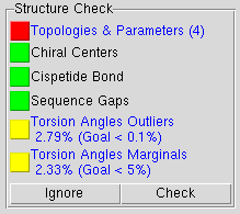
QwikMD checks the initial structure for structural inconsistencies in 4 different tests:
  • Topologies & Parameters: Comparison between the residues' name in the initial structure and the residues' name in the CHARMM36 topology files. Once a mismatch is detected, the residue is marked in red in the "Residues Table" and the correspondent chain is colored as "Throb" in the "Main Table". The system preparation phase cannot start before this warning is solved.
  • The easiest way to overcome the lack residue topologies and parameters is to delete the residue, which may not be desirable as the referred molecule might well be relevant. Thus, one has to provide QwikMD with the missing force field topology and parameters. If the topology and the parameters are available, i.e., in the literature, but not yet added to the force field, the user may add to QwikMD through Topology & Parameters Selection. These parameters can also be obtained from web servers, with varying levels of accuracy, such as CGenFF webserver. The most accurate and recommended method for furnishing missing parameters requires advanced knowledge, namely familiarity with the Force Field Tool Kit (FFTK) plugin in VMD. The ffTK plugin assists with the process of parameterization, employing quantum chemistry programs.
  • Chiral Centers: Detection of cis chirality errors in protein and nucleic acid structures using the Chirality plugin in VMD. For more information how to fix chirality errors please follow the Structure Check tutorial.
  • All amino acids but glycine have at least one chiral center at Cα. Threonine and isoleucine have an additional chiral center at Cβ. According to the D- / L- naming convention, naturally occurring amino acids are found in the L-configuration. Note, however, that D-amino acids do occur in biology, e. g., in cell walls of bacteria. Nucleic acids also have chiral centers. For example, in DNA the atoms C1', C3', and C4' are chiral, while RNA has an additional chiral center at C2'. Chirality is central to all molecular interactions in biological systems. A simple experiment demonstrates the principle: try to shake someone's left hand with your right.
  • Cispetide Bond: Detection of cis peptide bonds in protein structures using the Cispeptide plugin in VMD. For more information how to convert fix chirality errors please follow the Structure Check tutorial.
  • In naturally occurring proteins most peptide bonds are in the trans configuration. However, sometimes cis peptide bonds do occur. The vast majority of cis peptides is observed at a proline, Xaa-Pro, Xaa being any amino acid. But non-proline Xaa-non Pro cis bonds are also found in proteins, although they occur much less frequently than Xaa-Pro. The configuration of the peptide bond is central to the sort of secondary structure the protein backbone can adopt. It is easy to understand by imagining a normal α-helix and converting a trans peptide bond into its cis form. The result is that the hydrogen bond network stabilizing the helix is broken and the helix will be unstable in long simulation.
  • Sequence Gap: Detection of non-consecutive numbering of the protein and nucleic residues within each chain. If the residues sequence present a gap, another test is performed to evaluate if the residues are bonded, avoiding false detection of pre-crystallization sequence deletions. Due to the complex structure of carbohydrates (glycan), this test is not performed for such molecule types.
  • PDB Insertion Codes: Sometimes the initial structure presents insertion codes in the residues sequence. Rather than be numbered sequentially, some structures present residues numbering as 47, 47A, 47B and so on. This different numbering rises from the comparison between homologous proteins which have different chain lengths, and the authors who wants to preserve the reference among the different proteins use additional characters to identify non-matching residues between homologous sequences.

    QwikMD reorders the residues to avoid unintentional deletion of the residues presenting different insertion codes. During the loading process, the residues sequence is checked for the existence of insertion codes and new residues IDs are assigned to ensure sequential numbering. In the end of the check structure process, a warning message is prompted to the user followed by the reference table displaying the relationship between the initial and the new numbering sequence. The reference table is then saved in the "setup" folder, within the working directory during the preparation phase, in the file "Renumber_Residues.txt".
  • Torsion Angles Outliers/Marginals: Evaluation of the distribution of the φ and ψ backbone angles. The percentage of angles consider as Outliers and Marginals are good indicators of the stereochecimal quality of the structure. QwikMD uses the command line of Torsion Plot VMD plugin to perform this evaluation. For more information, please visit the Ramaplot Plugin.
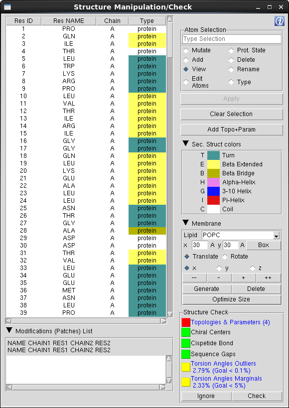
Membrane Top
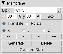
The "Membrane" field is activated when the Structure Manipulation/Check window is invoked from the Advanced Run. In here, one can defined the dimensions and position of the lipid bilayer. QwikMD uses the Membrane VMD plugin to generate the membranes.
  • Lipid: Membrane lipid composition. Only two types of lipid composition are currently available:
    • POPC: membrane 100% composed by 3-palmitoyl-2-oleoyl-D-glycero-1-Phosphatidylcholine
    • POPE: membrane 100% composed by 3-palmitoyl-2-oleoyl-D-glycero-1-Phosphatidylethanolamine
  • x/y entries: membrane dimensions in the x-axis/y-axis in Å. The initial position of the membrane is assigned to the center of the system currently selected.
  • Box: Draw the box where the membrane will be positioned.

    Note: Due to the slow process of building the membrane and to avoid rounding floating point arithmetic rounding errors generated during coordinates translation and rotation process, the position of the membrane is defined using a temporary box, and then the membrane is generated once. If one decides to change the position of the generated membrane, first the membrane must be deleted pressing the "Delete" button, reposition the box, and generate the membrane again.

  • Translate/Rotate: the action generated by the movers "--", "-", "+" and "++".
  • x / y / z: axis for translation/rotation.
  • -- / ++ buttons: membrane temporary box movers to translate the box by -5 Å or +5 Å, or rotate -15° or +15° over the selected axis.
  • - / + buttons: membrane temporary box movers to translate the box by -1 Å or +1 Å, or rotate -1° or +1° over the selected axis.
  • Generate: Generate the membrane according to the location and dimension of the temporary box.
  • Delete: Delete the previous generated membrane.
  • Optimize Size: Change the center and dimensions (orientation is not affected) of the membrane to ensure that the existence of at least 15 Å between protein maximum and minimum coordinates and simulation cell limits in the membrane axis.

    Note: The periodic boundary conditions dimensions, in the membrane axis, are determined by the membrane dimensions.

Modifications (Patches) List Top
During the structure preparation, the initial structure is split into individual segments, such as, the segment containing all protein residues belonging to the chain A, protein residues of the chain B and the segment containing all water residues belonging to the chain A (see psfgen tutorial). Often times, special modifications (patches) are necessary after the creation of the segments, such as a connection between two different protein segments, or a crosslink between an Heme group and the protein chain.

One can apply structure modifications by listing the sequence of patches, following the specific command format, "PatchName ChainID1 ResidueNumber1" or in cases of 5 arguments patches "PatchName ChainID1 ResidueNumber1 ChainID2 ResidueNumber2". The list of modifications can be found in the CHARMM36 topology and stream files with the keyword "PRES".

Simulation Setup & Control Top
In this section of QwikMD, one can prepare the system to be simulated, generate all the files necessary to run the MD simulation as well as perform the simulation using NAMD. To run an MD simulation with NAMD at least four files are required: a Protein Data Bank (pdb) file a Protein Structure File (psf), a force field parameter file and a configuration file. During the preparation steps, where the system might be solvated, ionized, among other procedures, several files are created.
QwikMD Output folder
QwikMD stores the files created in the preparation step in the "setup" folder, while all the files necessary to run the MD simulations are stored in the "run" folder. These two folders are created inside the main folder defined by the user in working directory window. With the same name as the folder created by the user, a file with .qwikmd extension allows the user to restore QwikMD interface to a saved state and load the simulations already executed.

QwikMD Output folder structure

  • InputFileName.qwikmd
  • InputFileName
    • InputFileName.infoMD
    • setup
      • Preparation auxiliary files
      • Intermediary pdb files
      • Intermediary psf files
      • Renumber_Residues.txt (if applicable Structure Check)
      • TopologyFiles.rtf
      • Topology+ParameterFiles.str
    • run
      • NAMDConfigurationFiles.conf
      • InputFileName_QwikMD.pdb
      • InputFileName_QwikMD.psf
      • ParameterFiles.prm
      • Topology+ParameterFiles.str
      • SimulationLogFiles.log
      • SimulationTrajectories.dcd
Simulation Setup & Control options
  • Save: Save all the operations performed and options to the QwikMD input file (*.qwikmd)
  • Load: Load a previous generated QwikMD input file. If one ore more protocol steps had been already performed, one can use the dialog window to the steps to be loaded into VMD.
  • Reset: Return QwikMD to the initial state and set all the options to the default value. If a simulation is being performed in "Live View" Mode, QwikMD will terminate the simulation during the reset process.
  • Live View: Run the simulation in "Live View" Mode. Within "Live View" Mode, one can visualize the simulation while it is being calculated, useful for demonstration purpose and for quick system inspection. During the "Livew View" simulation, one can also perform live analysis, in which the properties, like Root Mean Square Deviation (RMSD) and energies components are calculated and displayed, concurrently with the simulation calculation.

    WARNING: This option must be selected before pressing the button "Prepare".

  • Prepare: Prepare the system for simulation and generate the configuration files necessary to execute NAMD. The system preparation phase is composed by the following steps: structure manipulation operations selected by the user such as point mutations and protonation state assignment; membrane insertion; system solvation and salt addition to neutralize and achieve the desired concentration (if applicable). QwikMD keeps track of every options and operations performed by the user and stores the information in two log file: the QwikMD input file and "InputFileName".infoMD.
    • QwikMD input file (*.qwikmd) is a script compiling all the options selected and operation performed by the user and can be loaded back into QwikMD.
    • "InputFileName".infoMD is a human readable text file, where one can review all the steps taken regarding the system preparation, methods and the correspondent citation articles employed in the simulations and the analysis carried over the simulations.
  • Start Simulation: Execute the protocol step listed in the button text. In the case of "Live View" mode simulations, one can visualize and perform live analysis, otherwise, NAMD will be executed in the background and QwikMD and VMD will be inaccessible ("froze") until the simulation is completed.

    Easy Run: On "Easy Run" tab, one can extend the MD or SMD simulation step (depending on the current selected protocol) by pressing this button again, where a new MD or SMD simulation is started from the last point of the previous simulation. The extended simulation are numbered sequentially and latter loaded into QwikMD in the same order.

    Advanced Run: On "Advanced Run" tab, one can extend the last simulation on the current protocol by adding an additional step to the protocol and press the this button to start the simulation from the last point of the previous simulation. The extended simulation are numbered sequentially and latter loaded into QwikMD in the same order.

    Run Simulations On Supercomputers: To perform the simulations prepared with QwikMD on a supercomputer, one must copy the "run" folder to the the supercomputer file system and run NAMD following the procedures for the specific computer.

  • Pause: Pause a "Live View" simulation
  • Detach: Stop a "Live View" simulation without update the coordinates. Use this button it if anything goes wrong.
  • Finish: Stop a "Live View" simulation and update the coordinates.
  • Progress bar: Display the current progress of a "Live View" simulation.

    Note: During a "Live View" simulation, QwikMD gui is updated on a fix interval of simulation steps. If the simulation finishes before the completion of the interval, QwikMD can not detect the increment to update the progress bar as well as the simulation termination. In this case one must press "Finish" to enforce the update of QwikMD. The message Info) IMD connection ended unexpectedly; connection terminated on the VMD terminal window indicates that the simulation stopped/finished.

Load Results & Analysis Top
VMD is a powerful tool for analysis of structures and trajectories and should be used as a tool to think. Numerous tools for analysis are available under the VMD Main menu item Extensions - Analysis. In addition to these built-in tools, VMD users often use custom-written scripts to analyze desired properties of the simulated systems. VMD Tcl scripting capabilities are very extensive, and provide boundless opportunities for analysis. QwikMD provides the user with some of the most employed analysis tools, allowing also the analysis while performing live NAMD sections.
The combination of NAMD and VMD creates what we like to call the computational microscope. Analysis of molecular dynamics trajectories is a very important step in any study that aims to understand molecular details of protein complexes. Connecting dynamics to structural data from diverse experimental sources, molecular dynamics simulations permit the exploration of biological phenomena in unparalleled detail. Advances in simulations are moving the atomic resolution descriptions of biological systems into the million-to-billion atom regime, in which numerous cell functions reside. To read more about the advances in Molecular Dynamics simulations to study large and complex system check the link at the bottom of this window.
Load Results Top
After executing the simulation(s), one can load and analyze the MD trajectories. To load the trajectories on must load the QwikMD input file (*.qwikmd) using the "Load" button on the Simulation Setup & Control section. After load the input file, QwikMD will prompt the window "Loading Trajectories" where one can select the trajectories to be loaded into VMD.
  • Don't load water/solvent ion molecules or hydrogen atoms: trajectory pre-load treatment to remove the water/solvent ion molecules or hydrogen atoms and therefore reduce the size of the trajectory files to be loaded into VMD. Depending on the size of the trajectory, this step may take a long time to perform, however is only performed once per combination of selected options. This pre-treatment creates a new trajectory file (*.dcd) in the "run" folder with a suffix "_" In the subsequent loading This options uses the CatDCD program only available the Unix (Linux & Mac) versions of VMD.
  • Select Trajectories: select the trajectories to be loaded into VMD. Only the selected trajectories will be considered for analysis as well as the correspondent simulation log files, containing the values of the energy components (bonds, angles and etc.), SMD forces, temperature, volume and pressure.
  • Loading Trajectory Frame Step (Stride): select every Stride frames from the beginning to the end of the trajectory. Default value is 1, meaning loaded all frames stored in the trajectory file.
WARNING: the 32-bit version of the VMD is limited to load up to 4GB trajectory files (in total), which is the usual case of the VMD versions for Mac. To overcome this limitation, one must select a "Loading Trajectory Frame Step" greater than 1, or select the options to remove water and/or ion molecules and/or remove hydrogen atoms (if not needed for analysis).
Analysis Top
Either during a "Live View" simulation or after load the trajectories, QwikMD allows the user to perform common analysis in two analysis tabs: "Basic Analysis" and "Advanced Analysis".
Basic Analysis
Root Mean Square Deviation (RMSD): is the measure of the average distance between the atoms (usually the backbone atoms) of superimposed proteins. In the study of globular protein conformations, one customarily measures the similarity in three-dimensional structure by the RMSD of the Cα atomic coordinates after optimal rigid body superposition.
  • Region selection: the first atom selection regards the structure region where the RMSD will be calculated. One can use the drop-down menu to select the pre-defined selection OR type the atom selection in the text entry, using VMD atomselection syntax.
  • Align Structure: align each frame with the first frame loaded into VMD. Like the "Region Selection", one can select the alignment target region using the drop-down menu OR typing the atom selection in the text entry, using VMD atomselection syntax.

More advanced options for RMSD analysis can be done with VMD plugins available in VMD Main menu item Extensions - Analysis. To read more about VMD and its plugins check the VMD plugins webpage.

Energies: QwikMD provides an easy-to-use interface to plot the energies reported in the NAMD log files during a simulation. Here one can plot the sum of all Potential energies (bonds, angles, dihedrals, impropers, electrostatics and VDW); Kinetic energy (atoms energy of motion) and the Total energy (sum of the Potential and Kinetic energies).
Thermodynamics: To track the evaluation/equilibrium of the MD simulation is current practice to analyze the Temperature, Pressure and the Volume values. These values are calculated by NAMD and reported in the log file and can be easily plot by QwikMD. As the default MD simulations performed in qwikmd are carried in the isothermal-isobaric ensemble (NpT), the number of atoms (N), pressure (p) and temperature (T) are kept constant by employing thermostat and barostat, it is interesting to observe small variation of T and p values around the user defined values. As in the example image on the right, when the simulation is prepared to run in Implicit Solvent model or in vacuum, the values of "Pressure" and "Volume" are not available since there is not an explicit definition of simulation box.
Advanced Analysis
Hydrogen Bonds (H bonds): The Hydrogen bonds window shows the number of hydrogen bonds formed throughout a trajectory. A hydrogen bond is formed between an atom with a hydrogen bonded to it (the donor, D) and another atom (the acceptor, A) provided that the distance D-A is less than the cut-off distance (3.5 Angstroms) and the angle D-H-A is less than the cut-off angle (30 degrees). Only the polar atoms (Fluorine, Oxygen, Nitrogen and Sulfur) are considers during the hydrogen bonds calculation. QwikMD allows the user to count the number of hydrogen bonds on the fly per each step. The hydrogen bonds can be calculated for the internal hydrogen bonds of the protein, between solute (usually protein) and water molecules, or between two atom selection. For more information, please visit VMD HBonds plugin.
SMD Forces: There are two typical protocols of SMD: one in which pulling velocity is held constant and one in which applied force is constant. Typically, part of the studied system (e.g. an atom in a protein) is restrained by a harmonic potential. Forces are then applied to specific atoms at either a constant velocity or a constant force. Here one user can plot the Force vs Time and Force vs Distance graphics. The Force profiles can be compared with single-molecule force spectroscopy (SMFS) experiments, which are usually performed with optical tweezers and/or atomic force microscopes (AFM).
Root Mean Square Fluctuation (RMSF): When a dynamical system fluctuates about some well-defined average position, the RMSD from the average over time can be referred to as the RMSF or root mean square fluctuation. The size of this fluctuation can be measured, for example using Mössbauer spectroscopy or nuclear magnetic resonance, and can provide important physical information. The options available for the RMSF calculation are very similar to the ones in the RMSD, where in the RMSD, one can select the frame range to be included in the calculation.
Solvent Accessible Surface Area (SASA): Calculation of the Solvent-Accessible Surface Area (SASA) of the selection defined in "Atom Selection" during the simulation, presenting only the values for the selection defined in the "Restriction Selection". The #S value in the table represents the total SASA value, while the rest of the table is populated with SASA values for each selected residue. SASA calculation is based on the measure sasa command. For more information, please visit the measure command webpage.
Contact Area: Based on the SASA calculation, the contact area is calculated based on the surface area of the "Selection 1" exposed to the "Selection 2" and vice-versa. The calculation of the contact area is performed in two steps, where the SASA is calculated for the residues of the "Selection 1" distanced 5 Å of the "Selection 2" in the absence and presence of the "Selection 2". The difference between the two will give the surface area of the "Selection 1" exposed to the "Selection 2" (#S1). The same calculation is performed, but in this case for the Selection 2 (#S2).
Specific Heat, Temperature Distribution, Maxwell-Boltzamnn Energy Distribution, Temperature Quench: These analysis illustrate four examples of statistical mechanics properties that can be calculated from an MD simulation trajectory. For more information, please follow the analysis section of the namd tutorial.