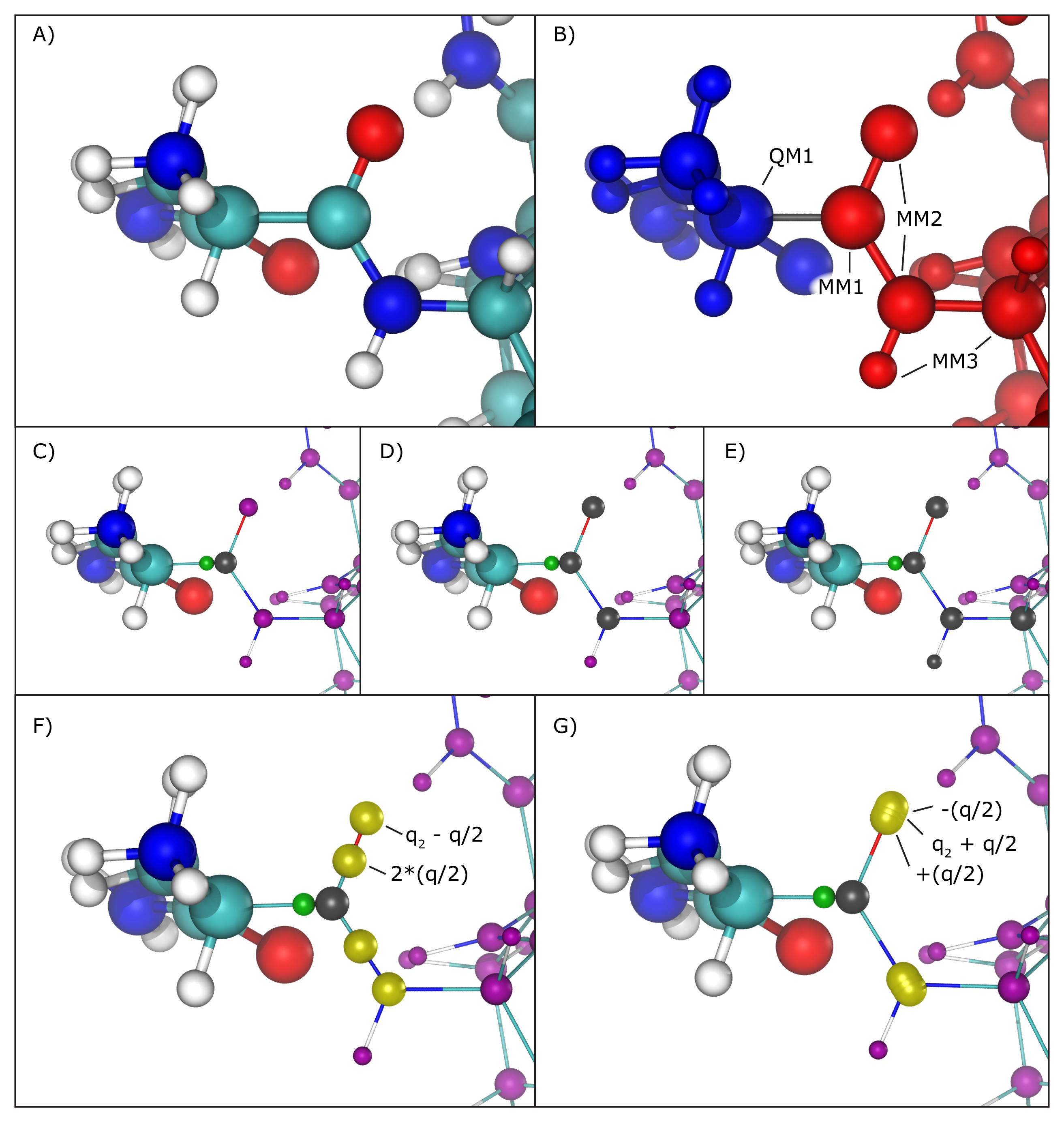
Hybrid QM/MM simulations of biomolecular systems often present situations where only a portion of a molecule should be treated quantum mechanically, usually to save computational resources since the cost of simulating QM regions rises rapidly with the number of simulated toms. In order to deal with chemical bonds that are split by the QM/MM division of the biomolecular system, that is, bonds that have one atom in the quantum (QM) region and another in the classical (MM) region (we will call these ``QM/MM bonds"), NAMD makes approximations to the molecular system in order to bridge differences in simulation type (QM vs. MM), and minimize errors involved in the QM/MM division of the system (Figure 17 A and B).
|
As previously mentioned, the information regarding atoms in the QM region is passed on to the chosen QC software, that is, their respective positions and element types, but in order to maintain (or approximate) the effect of the chemical bond between the QM atom and the MM atom, NAMD creates and places a link atom (usually a hydrogen) along the ``broken" QM/MM bond. The user can fine-tune this process by choosing the method of placement of the link atom and even the element of such atom (keywords ``qmBondDist" and ``qmLinkElement").
The introduction of the link atom will invariably place it very near the classical atom involved in the QM/MM bond, therefore the use and placement of partial charges from classical atoms becomes highly relevant. Under the mechanical embedding scheme, the QC software only receives the atoms in the QM region and the link atoms created to approximate QM/MM bonds, so no manipulation of partial charges is required. On the other hand, usual QM/MM simulations are done under the electrostatic embedding scheme, in which case the partial charges of classical atoms involved in the QM/MM bonds and classical atoms directly connected to them require special treatment.
Several methods have been proposed to handle this situation, and the QM/MM interface developed here implements the most widely accepted ones. One can be chosen using the ``qmBondScheme" keyword (Figure 17 C to G). In all implemented methods, the classical atom participating in the QM/MM bond (MM1 atom) does not have its partial charge passed on to the QC software, since this would create excessive repulsion (or attraction) on the link atom. This is, in fact, the entirety of the ``Z1" method: ignoring the partial charge of the MM1 atom. Analogously, ``Z2" and ``Z3" ignore all partial charges up to MM2 and MM3 atoms, respectively (Figure 17 C to E).
The Redistributed Charge and Dipole (RCD) method
(Figure 17 F)
is more elaborate, as it rearranges the partial charge of the
MM1 atom (indicated as ![]() ) so that the total charge of the region
is maintained as well as the dipole moments of the bonds between
MM1 and MM2 atoms. This is done by creating ``virtual" point charges,
which are passed on to the QC software as if they represented
partial charges of classical atoms. More specifically, the RCD method
creates a virtual point charge in the middle of all MM1-MM2 bonds
with a charge of
) so that the total charge of the region
is maintained as well as the dipole moments of the bonds between
MM1 and MM2 atoms. This is done by creating ``virtual" point charges,
which are passed on to the QC software as if they represented
partial charges of classical atoms. More specifically, the RCD method
creates a virtual point charge in the middle of all MM1-MM2 bonds
with a charge of ![]() , where
, where ![]() is the number of
MM2 atoms connected to MM1, and also subtracts a charge
is the number of
MM2 atoms connected to MM1, and also subtracts a charge ![]() from each of the MM2 atoms, so that the total charge of the region
remains constant while approximating the dipole moment of the
MM1-MM2 bonds. This way there will be no point charge placed at the
position of the MM1 atom, but its partial charge is not simply removed,
it is redistributed.
from each of the MM2 atoms, so that the total charge of the region
remains constant while approximating the dipole moment of the
MM1-MM2 bonds. This way there will be no point charge placed at the
position of the MM1 atom, but its partial charge is not simply removed,
it is redistributed.
A similar approach is taken by the Charge Shifting (CS) method
(Figure 17 G).
In this case, the MM1 partial charge is equally
distributed across the MM2 atoms, and two virtual point charges
are placed along the direction of the MM1-MM2 bond, one before
the MM2 atom and one after, each one with a charge of ![]() and
and ![]() respectively. This method will also keep the
total charge of the region constant while trying to preserve
the local dipoles formed by all MM1-MM2 bonds.
respectively. This method will also keep the
total charge of the region constant while trying to preserve
the local dipoles formed by all MM1-MM2 bonds.
Along with the gradient over all QM atoms, NAMD can also use the partial charge derived from the QC calculation to update the charge distribution of atoms in the QM region. When a QM/MM bond exists, however, part of the charge of the region will be placed on the link atom, and in order to keep the charge of the QM region constant, the link atom charge is re-distributed on the QM region. This seemingly simple mechanism can cause problems unless special care is be taken when deciding which bond will mark the division of QM and MM regions.
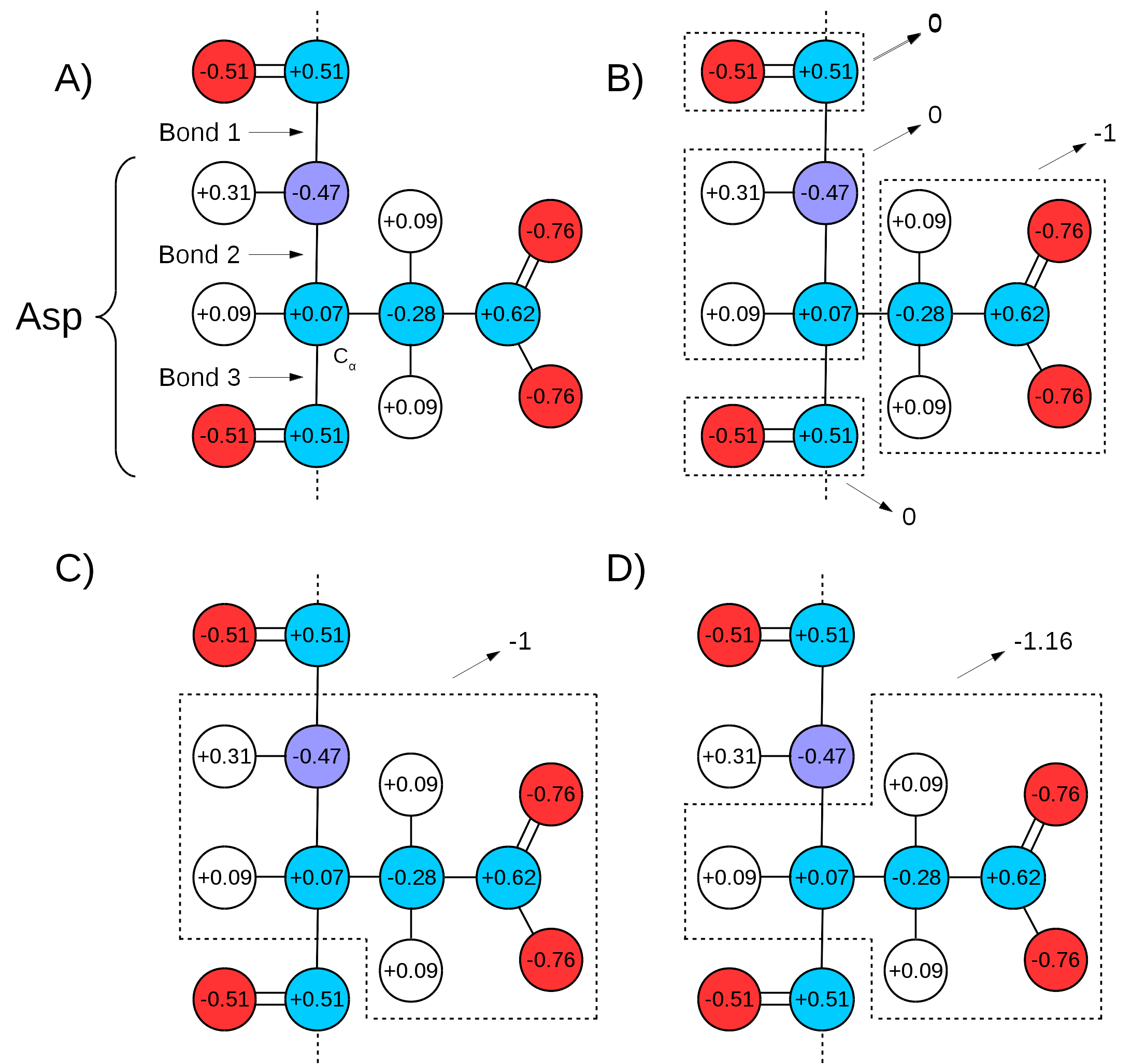
Many force fields divide the topologies of biomolecules in ``charge groups" (Figure 18 A and B). What this means is that not only will the partial charges of all atoms of a molecule add up to the whole number that represents the charge of the molecule, they will also add up to whole numbers in sub groups of atoms (look for the ``GROUP" statements in http://www.ks.uiuc.edu/Training/Tutorials/namd/namd-tutorial-unix-html/node24.htmlto see an example). Therefore, one needs to make sure that the chosen QM/MM bond(s) sits in between ``charge groups", so the total sum of partial charges of atoms defining a QM region is a whole number. This is especially important in order to keep the total charge of the system constant. Since the QC calculation will always distribute a whole charge over all atoms of a system (QM atoms plus a link atom), if the partial charge of QM atoms is not initially a whole number, it will be forced into a whole number after the first QC step, where the charge of the link atom is distributed over the QM region. This will create a mismatch between QM and MM charges, changing the total charge of the entire system (QM plus MM regions).
|
An example can be seen in Figure 18,
bonds 1 and 3 are chosen as the QM/MM bonds,
the charge distribution seen in Figure 18 C shows
a whole charge for the QM region (and consequently for the MM region).
Therefore, any charge placed on link atoms can be redistributed
to the QM atoms with no change in total system charge. However,
if bonds 2 and 3 are chosen for the QM/MM bond
(Figure 18 D),
the charge of the MM region would be ![]() , while the charge
of the QM region would be
, while the charge
of the QM region would be ![]() . Since the QC calculation would
place a pre-determined whole charge on the region (
. Since the QC calculation would
place a pre-determined whole charge on the region (![]() , in this case),
the updated charge of the QM region after the first simulation step
would change the total charge of the system to
, in this case),
the updated charge of the QM region after the first simulation step
would change the total charge of the system to ![]() , in this example.
, in this example.