Next: Appendix
Up: Bionanotechnology Tutorial
Previous: Simulation setup and protocols
Contents
Subsections
Simulations of DNA permeation through nanopores
In the second unit, you will learn how to
manipulate DNA molecules and simulate
their permeation through a synthetic nanopore.
- 1
- Enter cd ../5_manipulate_dna/ to start this section.
- 2
- In the Tk Console type
| mol load psf dsDnaAmber.psf pdb dsDnaAmber.pdb |
|
In the Graphical Representations window, set the
Drawing Method to Licorice and the
Coloring Method to ResName.
- 3
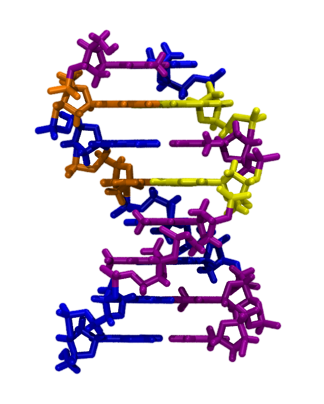
- You should now see an 8-basepair molecule of double-stranded
DNA (dsDNA), colored by the residue names ADE, CYT, GUA, and THY; which
correspond respectively to the bases adenine, cytosine, guanine, and
thymine. (See Fig. 5. Try setting Selected Atoms in the Graphical
Representations window to resname ADE, resname CYT, resname GUA, and resname THY in turn. Which colors correspond
to which bases?
Figure 5:
Double-stranded DNA colored by base type.
|
|
- 4
- To determine the base sequence for the first strand, type the
following in the Tk Console:
| set a [atomselect top "segname ADNA and name C1'"] |
|
| puts [$a get {resid resname}] |
|
| $a delete |
|
What is the sequence of the first
strand (segment name ADNA)? What is the sequence of its complementary
strand (segment name BDNA)?
- 5
- There are several sets of parameters available for molecular modeling
of DNA.
We'll use the AMBER topology
given in cornell.rtf and the interaction parameters given in
cornell.prm. Another popular model of DNA uses the Charmm
topology and parameter set.
The script convertDnaToCharmm.tcl can produce
a Charmm model from our AMBER model. The script applies patches using
psfgen to change the topology from that of the AMBER model to
that of the Charmm model using the Charmm topology file top_all27_prot_na.inp. Execute this script by typing source
convertDnaToCharmm.tcl in the Tk Console.
- 6
- In the Tk Console, enter
mol load psf
dsDnaCharmm.psf pdb dsDnaCharmm.pdb. Set the Drawing Method
to Licorice, the Coloring Method to Molecule, and Selected Atoms to all for both the AMBER
DNA that we loaded earlier and the Charmm DNA. No difference in
structure between the AMBER model and the Charmm model should be
apparent. In the Tk Console, enter mol delete all.
- 7
- Now we would like to produce single-stranded DNA (ssDNA) from
dsDnaAmber.psf and dsDnaAmber.pdb. The script removeResidues.tcl deletes the residues of all atoms in a given
selection. Open the script in your text editor. The first and second
DNA strands have the segment names ADNA and BDNA, respectively. Set
the value of selText in line 6 to segname BDNA so
that the script will delete the second DNA strand. Save your changes
and execute the script.
- 8
- Let's check that we produced the ssDNA correctly. Enter mol load psf ssDna.psf pdb ssDna.pdb in the Tk Console. After
examining your 8-mer ssDNA, type mol delete all.
ssDNA is much more flexible than dsDNA and easily bends into various
conformations. The details of these conformations can be important for
applications of bionanotechnology. For example, if ssDNA is to pass
through a nanopore device, such as is proposed for a means of fast
sequencing, it must be aligned somewhat along the axis of the
pore. Molecules lying in the plane of the membrane or contorted in
certain ways can make translocation more difficult or impossible. For
this reason, we want the ability to easily generate any desired DNA
conformation in silico.
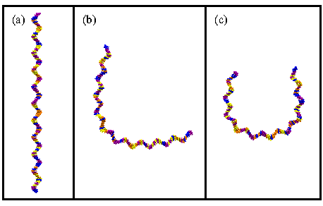
Figure 6:
Shaping single-stranded DNA. (a) The DNA begins in a straight
conformation. (b), (c) Bending the DNA with Sculptor using two
different paths as described in the text.
|
|
- 9
- Here we will use the VMD script sculptor.tcl to shape
ssDNA to our will. In the Tk Console, enter the following
lines to load a 110-mer ssDNA molecule and open Sculptor:
| mol load psf ssDnaLong.psf pdb ssDnaLong.pdb |
|
| source sculptor.tcl |
|
| sculptorGui |
|
The Sculptor window should open.
The script will map any long molecule aligned along the  -axis to
a cubic spline whose form is given by the points in Path.
If we are careful, the cubic spline allows us to bend the ssDNA smoothly,
leading to conformations, that with some equilibration, could occur in nature.
However, using Sculptor on structures that are not relatively
straight along the -axis, applying a tortuous path, or
pressing the Sculpt button more than once
without undoing the last operation will result in highly distorted
and unphysical conformations. If this happens, simply reload the molecule.
-axis to
a cubic spline whose form is given by the points in Path.
If we are careful, the cubic spline allows us to bend the ssDNA smoothly,
leading to conformations, that with some equilibration, could occur in nature.
However, using Sculptor on structures that are not relatively
straight along the -axis, applying a tortuous path, or
pressing the Sculpt button more than once
without undoing the last operation will result in highly distorted
and unphysical conformations. If this happens, simply reload the molecule.
- 10
- Let's start by bending ssDNA into an L-shape. Delete the
contents of Path, and type {0 0 1} {0 0 0} {1 0
0}. Press Sculpt. Rotate the molecule a bit and then
press Undo. Your result should look like
Fig. 6(b).
- 11
- Now we'll bend the ssDNA in a U-shape. Delete the contents of
Path and type {0 1 2} {0 1 0} {0 -1 0} {0 -1
2}. Imagine the positions of these coordinates in space. You
should see that they form three sides of a rectangle. Production of a
cubic spline from these control points will yield a U-shape as shown
in Fig. 6(c). Press Sculpt. Undo this and
then produce a few conformations of your own. Close Sculptor when you
are finished. Then enter mol delete all.
- 1
- We now will combine our 8-mer ssDNA molecule with the
 nanopore. Execute the script combine.tcl, which will create
pore+dna.psf and pore+dna.pdb. As shown below, the
script combines the pore we created in Section 1.2 with the ssDNA
using psfgen. The script is rather general, but can run into
problems if segment names are duplicated between the scripts.
nanopore. Execute the script combine.tcl, which will create
pore+dna.psf and pore+dna.pdb. As shown below, the
script combines the pore we created in Section 1.2 with the ssDNA
using psfgen. The script is rather general, but can run into
problems if segment names are duplicated between the scripts.
combine.tcl
# Input:
set psf0 ../1_build/pore.psf
set pdb0 ../1_build/pore.pdb
set psf1 ssDna.psf
set pdb1 ssDna.pdb
# Output:
set finalPsf pore+dna.psf
set finalPdb pore+dna.pdb

# Load the topology and coordinates.
package require psfgen
resetpsf
readpsf $psf0
coordpdb $pdb0
readpsf $psf1
coordpdb $pdb1

# Write the combination.
writepdb $finalPdb
writepsf $finalPsf
- 2
- We've added the ssDNA without regard for the position of the pore.
We now need to adjust the position of the molecule so that
it is in a reasonable position for our translocation simulation.
What is the charge of DNA? Which way will it move in an
electric field pointing along the -axis?
Enter mol load psf pore+dna.psf pdb pore+dna.pdb
in the Tk Console.
Examine the system in the VDW representation.
Using selection text like
segname ADNA and within 4.0 of resname SIN
allows us to see where the DNA has been placed too close
to the
.
Type the following commands into the Tk Console:
| set sel [atomselect top "segname ADNA"] |
|
| $sel moveby {4 1 7} |
|
| set all [atomselect top all] |
|
| $all writepdb pore+dna.pdb |
|
| $sel delete |
|
| $all delete |
|
VMD will not automatically update a selection defined by within
commands after the ssDNA has been moved. To see the changes, simply
change one letter in the Selected Atoms box, change it back,
and press Enter. When you are convinced that the ssDNA is not too
close to the
, enter mol delete all.
![\framebox[\textwidth]{
\begin{minipage}[r]{.75\textwidth}
\noindent\small\text...
...on than before. Save the
result as {\tt pore+dna\_other.pdb}.}
\end{minipage} }](img72.gif)
- 1
- We've been running a lot scripts in our VMD session, some of
which may have large global variables. This might be a good time to
exit VMD and start a new VMD session to free any memory in these
variables.
- 2
- Enter cd ../6_current_dna/ in the Tk Console.
Execute the solvation scripts addWater.tcl, cutWaterHex.tcl, and addIons.tcl in sequence.
- 3
- To save the time it takes to equilibrate the system, we've
included an equilibrium system (sample*) with which you can continue.
- 4
- Calculate the value of eField necessary to apply 20 V
along the
 -axis of the system with data from sample.xsc as
you did in Section 1.6. Place this value in the configuration file
run0.namd and execute NAMD with this file.
-axis of the system with data from sample.xsc as
you did in Section 1.6. Place this value in the configuration file
run0.namd and execute NAMD with this file.
- 5
- Execute the script electricCurrentZ.tcl to determine
the ionic current. How does it compare with what you measured with no
DNA in the system?
- 1
- Enter cd ../7_translocate/. In production simulations,
translocation would be performed in solution. However, due to time
constraints, we'll perform the translocation simulation in vacuum and
then analyze the provided trajectory for a similar simulation in
solution. We will also be using only short-range electrostatics (with
a 12 Å cutoff) instead of PME electrostatics because the vacuum
system has a nonzero charge. Electrostatic cutoffs are not recommended
for most production simulations.
- 2
- Execute constrainSilicon.tcl.
- 3
- Run the NAMD configuration scripts shown in the table below
sequentially. If you generated the pore with InorganicBuilder, you
need to change cellBasisVector1 and cellBasisVector2 in
eq0.namd to those you recorded. The final simulation may take
several minutes to run, so if you are short on time you may want to
skip this step and the one that follows.
| NAMD script |
steps |
description |
| eq0.namd |
201 |
minimization |
| eq1.namd |
500 |
raise temperature from 0 to 295 K at constant  |
| eq2.namd |
1000 |
constant  and Langevin thermostat and Langevin thermostat |
| run0.namd |
8000 |
electric field 150 kcal/(mol Å e) at constant |
- 4
- View the resulting trajectory in VMD by entering mol
delete all and mol load psf pore+dna.psf dcd run0.dcd. Change
the representation to VDW. Does the
ssDNA translocate from one side of the pore to another?
- 5
- Since your simulation was performed in a vacuum, we cannot
analyze the ionic current. For this reason, the trajectory translocate.dcd along with the structure translocate.psf and
extended system translocate.xsc has been provided. The data is
from a 6 V translocation simulation of dsDNA. Execute electricCurrentZFrame.tcl to calculate the ionic current for this
trajectory. Unlike the script of a similar name we used
previously, electricCurrentZFrame.tcl records the time in DCD
frames, instead of nanoseconds, to facilitate comparision with the
trajectory. The results are placed in the file curr_6V.dat.
- 6
- The script trackPositionZ.tcl operates in much the same
way as
electricCurrentZFrame.tcl except that it determines the
center of mass of the DNA relative to the center of the pore instead
of the current. Enter source trackPositionZ.tcl. The -position
of the center of mass is stored as a function of frame number in pos_6V.dat.
- 7
- Open the trajectory in VMD with the following commands:
| mol delete all |
|
| mol load psf translocate.psf dcd translocate.dcd |
|
In the Graphical Representations window, change
Selected Atoms to resname SIN and y > 0. Change the
Drawing Method to Beads. Create a new representation with
the selection segname ADNA BDNA and the drawing method VDW.
- 8
- Now plot current versus frame (curr_6V.dat) and
center-of-mass position versus frame (pos_6V.dat) and compare
it with the events that take place in the trajectory. How does the
passage of the DNA change the current?
Next: Appendix
Up: Bionanotechnology Tutorial
Previous: Simulation setup and protocols
Contents
www.ks.uiuc.edu/Training/Tutorials
![\framebox[\textwidth]{
\begin{minipage}[r]{.75\textwidth}
\noindent\small\text...
...his section. How does the presence of DNA affect the current?}
\end{minipage} }](img73.gif)
![\framebox[\textwidth]{
\begin{minipage}[r]{.75\textwidth}
\noindent\small\text...
...tion. Does the difference in conformation change the
results?}
\end{minipage} }](img74.gif)
![\fbox{
\begin{minipage}{.2\textwidth}
\end{minipage} \begin{minipage}[r]{.75\te...
...ets et al., \textit{Nano Letters} \textbf{6}, 89--95
(2006). }
\end{minipage} }](img75.gif)
![\framebox[\textwidth]{
\begin{minipage}[r]{.75\textwidth}
\noindent\small\text...
... using the files
{\tt ubiquitin.psf} and {\tt ubiquitin.pdb}.}
\end{minipage} }](img76.gif)